Inserting Data Cables
Inserting Data CablesData cables carry data signals, such as network, DMX, and audio information, from controllers to the various devices, or from device to device.
Data cables can be automatically added to the drawing; see Creating a Data Cable Chain.

To insert a data cable:
Click the Data Cable tool from the Spotlight tool set.
Click a polyline drawing mode from the Tool bar. For more information on the polyline drawing modes, see Dessiner une polyligne.
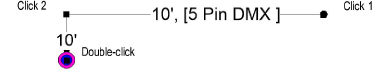
Click to place the start of the cable, and draw the cable polyline, clicking at each vertex. Double-click to finish drawing the cable.
The first time you use the tool in a file, a properties dialog box opens. Set the default properties, and click OK.
After placement, the cable path can be adjusted with the Reshape tool. The properties can be edited from the Object Info palette.
► Cliquez pour afficher/masquer les paramètres.
Paramètre |
Description |
Cable Run ID |
Names the cable run, which is useful for labels, schedules, and other worksheets |
Universe |
Specifies the universe of the data cable |
Rack ID |
Names the rack to which the cable connects |
Box ID |
Provides the distribution box name |
Port ID |
Names the port where the cable plugs in |
Loom ID |
Names the loom or bundle that includes the cable |
Tape Color Code |
Identifies the cable with a color code, which can be used to label racks and breaks |
Connector |
Select the type of connector |
With Terminator |
Displays the data cable with a DMX terminator indicator; the number of terminators is tracked for reporting purposes
|
Terminator Angle |
Sets the angle for displaying the terminator indicator |
Adapter |
Select the type of adapter, or select None if there is no adapter |
Adapter 2 |
Select the type of second adapter, or select None if there is no second adapter |
Location |
Provide a name for the jumper cable location for informational purposes |
Cable Path Length |
Displays the total length of cable required for the cable run; the label displays how much extra (unused) cable is present |
Unit Weight |
Sets the weight of the cable per unit of distance, for example, 2 kg/m |
Total Cable Weight |
Displays the weight of the entire cable |
Total Vertical Distance |
If the cable needs to travel vertically (to go around an opening, for example), the vertical distance is set for each part. This parameter displays the total vertical distance required. |
Calculate Parts |
Automatically determines the parts, or segments, of cable lengths needed to make up the cable run, using the fewest possible number of connections. The drawn cable is divided into parts, up to a total of nine parts, according to the available cable lengths in stock; each part displays with its own data. |
Stock Lengths |
Displays the available lengths of cable as set in the cable preferences |
Part __ |
Displays the length of each cable part |
Part __ Vert Dist |
Displays the vertical distance, if any, required for the part to travel around obstacles |
Part __ Loom ID |
Identifies the loom or bundle that includes this section of cable |
Cable Break __ ID |
Identifies the name of any cable break |
Part Total |
Displays the total length of cable used when all the parts are added |
Include All Vertices |
When the jumper cable is drawn by the Make Data Cable Chain command, actual distances required may be higher than expected because the cables are not drawn in a straight line. Deselect this option to account for the data cables not being drawn in a straight line, providing a more realistic length estimate. |
Part Total Is |
Displays the extra length of cable available |
Inventory ID |
Enter an optional inventory code for the cable |
User Field ___ |
Adds optional notes or comments about the cable, useful for reporting purposes. Field 3 is for entering a number only. |
Display On Drawing |
Enables the display of cable information on the drawing
|
Mark Connections |
Displays a marker and the cable length information where a cable connection is located
|
Lock Labels to Standard Position |
Restores text labels to their default positions, and prevents them from being moved |
Label Text Size |
Sets the text font size for the cable’s labels |
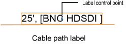
Display Length |
Displays the cable length in the label along the cable path |
Display Connector |
Displays the name of the connector type in the label along the cable path |
Horizontal Length Text |
Adjusts the cable path label to match the angle of the cable part; deselect the option to keep the text horizontal |
Display Start Label |
Adds a label at the start of the cable run; enter the text to display. The label has its own control point for adjusting its location. |
Start Label Text |
Enter the start label text |
Display End Label |
Adds a label at the end of the cable run; enter the text to display. The label has its own control point for adjusting its location. |
End Label Text |
Enter the end label text |
Opens the Classes dialog box, to specify class naming for the cable labels. This allows the labels to be set to visible, grayed, or invisible. Use the suggested standard class, select a class from the list of classes present in the drawing, or create a new class. Select <Data Cable Class> to place the labels in the same class as the data cable. ● Class Prefix: Specifies an optional default root class naming standard for the cable labels; click Use Standard Classes to begin all label class names with the prefix, so that they are sorted together. ● Use Standard Classes: Sets the class name for the label to the default suggested standard name, using the Class Prefix if there is one. ● Labels: Specifies the class name standard to use for the cable labels. |
|
Vertex parameters |
Edits the vertices of the path object that the cable is based upon; see Éditer la géométrie |
~~~~~~~~~~~~~~~~~~~~~~~~~
Selecting, Refreshing, and Converting Cables